Morara MT 2500 HD
Morara MT 2500 HD: the double wheel carriage grinding machine
The new MT-2500 HD is the high-performance grinding machine designed primarily for machining drive shafts and railway axles. The two independent wheelheads, the different configurations available (from 1 to 4 wheels for each unit) and the options make it a highly flexible machine, capable of satisfying multiple processing needs, drastically reducing processing times. Morara MT 2500 HD is the ideal and reference grinding machine for the railway and heavy component industry.Details that make the difference
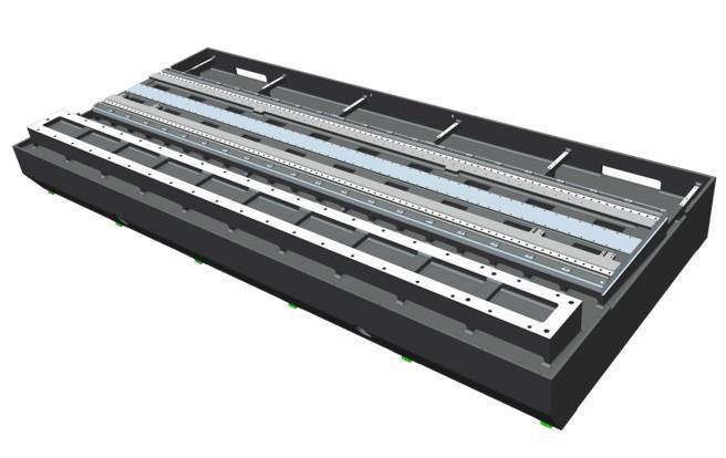
Cast iron base
Stabilized and ribbed cast iron base equipped with peripheral channels for coolant circulation. This machine was designed by using advanced techniques of 3D parametric modelling and FEM analysis. Its heavy structure (around 18 tons) provides very high vibration damping.
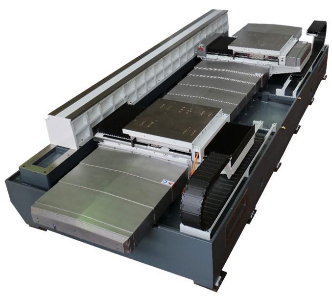
Hydrostatic guides and linear motors
The machine architecture is based on two independent wheelhead units mounted on crossed guides, i.e. a longitudinal unit (Z1 and Z2 axes) and a transverse unit (X1 and X2 axes), plus a fixed workpiece support and a head drive.
The main axis drives (Z1, Z2, X1, X2) are driven by linear motors for improved dynamic performance and easy system maintenance. The sliding guides of the main axis are of the hydrostatic type to preserve the dynamic characteristics of the machine.
The two tool turrets are equipped with an automatic CNC B axis rotation system, motorized wheel-holder spindles that run on very high-precision rolling bearings, suitable for standard and high cutting speeds with CBN wheels (120 m/s).
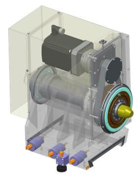
Workhead
The universal workhead, with fixed and rotating spindle, is perfect for overhang and between-center grinding. Made with high-precision bearings, which guarantee maximum roundness accuracy of less than 0.001 mm, the new workhead can be on an adjustable base, with the option of a device for micrometric adjustment. Progressive speed variation is performed by means of a digitally-controlled AC Brushless motor, while to facilitate the movement during machine set-up, the unit is equipped with a pneumatic lightening device.
It is also possible to have a workhead equipped with C Axis, for machining non-round pieces such as cams, eccentrics, regular polygons, threads and customized profiles.
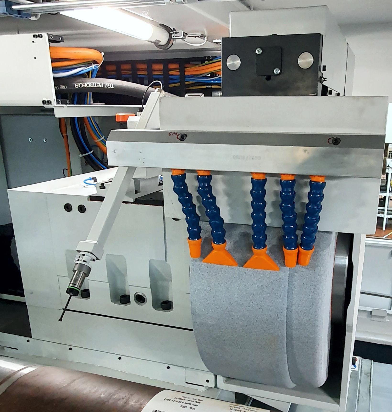
Wheel holder unit
The two wheel-holder carriages allow simultaneous machining on the same piece. The adoption of crossed guides, transverse "X" axis and longitudinal "Z" axis, allows to minimize the overall dimensions on the ground by rationalizing the arrangement of the fluidic and electrical systems. The carriage runs on high precision linear guides, by means of digitally regulated linear motors.
The numerous configurations of the wheelhead, which can be equipped with conventional wheels, can be effectively used thanks to the freely programmable orientation of the wheel carriage (Axis B), optional.
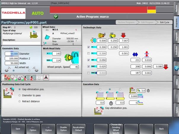
Software Tool Operator Package
Our interactive T.O.P. (Tool Operator Package) grinding software takes the operator step-by-step through the entire machine operation, easily and in compliance with safety regulations. The software makes it easy to manage automatic grinding cycles; roughing, semi-finishing, finishing and quenching during plunge and pendulum cycles.
The developed man-machine interface uses a few simple pages with graphic support. The operator can set the operations to be performed for set-up via wizards and for the execution of all available machining operations.
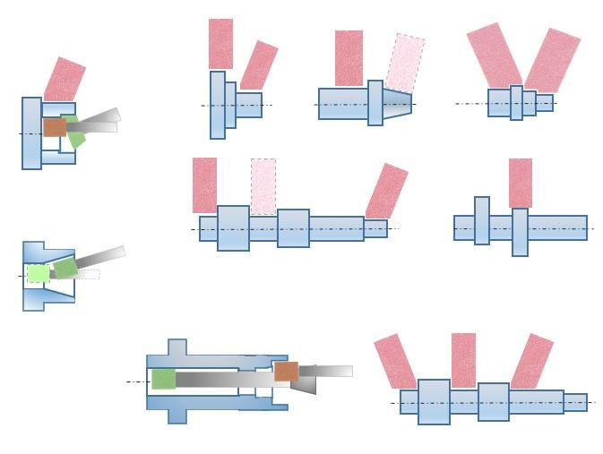
Discover the possible workings
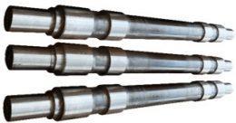
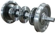
Morara MT 2500 HD grinding diameters from 50 mm to 600 mm, piece length up to 3000 mm, internal holes 300 mm deep with standard spindles and quill.
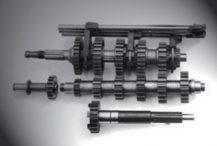
It is also used for the machining of components for the aeronautical industry; is able to grind external and internal diameters, conical surfaces and side faces in a single positioning, internal and external spherical surfaces.
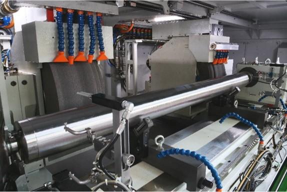
Operation video: watch a functioning Morara MT 2500 HD
Technical features
| Max grinding diameter | 350 mm ( opt. 600 mm)(1) |
| Point height | 255 mm (opt. 330 mm ) (1) |
| Max distance between points | 2.600 mm (opt . 3.000 mm) (1) |
| Max piece weight between centers | 2.000 kg (opt. 3000 kg) (1) |
| Total machine weight (approx.) | 36.000 kg |
| Total installed power (approx.) | 110 kW |
| Max grindable length | 2.800 mm |
| Minimum distance between wheel 1 and wheel 2 | 600 mm < / b> |
| Wheel 1 approach angle | 0 ° – 15 ° |
| Wheel 2 approach angle | ± 5 ° |
| B-axis under wheel 2 (with B-axis option) | ± 5 ° (opt. -15 ° – 210 °) (1) |
| B axis orientation resolution | 0.0001 ° |
| Max travel of Z1 and Z2 axes (with linear motors) | 2,500 mm |
| Max axis speed Z1 and Z2 | 20 m / min |
| Max travel of X1 and X2 (with linear motors) | 500 mm |
| Max speed of X1 and X2 axes | 20 m / min |
| Hydrodynamic wheel spindles (*) | |
| Wheel size | 760x340x304.8 mm |
| Motor power | 46 kW |
| Max wheel peripheral speed | 50 m / sec |
| (*) Electrospindles available for different confi gurations | |
| Universal WORK HEAD | ASA6 (8) -Morse 6 |
| Programmable speed | 10-200 rpm |
| Max spindle torque | 600 Nm |
| Hydraulic TAILSTOCK | Morse 6 |
| Quill diameter | 140 mm |
| Max stroke | 120 mm |
| Part cylindricity correction | + -0.15 mm |
| Notes: (1) Subject to technical verification of the machine equipment. | |


